Arduino Basics (en)
A special feature of microcontrollers is that we can change the logic through programming. In this workshop, we will use Arduino - a microcontroller platform which was developed at the Interaction Design Institute Ivrea especially for interaction design students. Arduino consists of a microcontroller board and its own integrated development environment (IDE) which makes it possible to program the board via USB.
Here is a documentation on the history and meaning of the Arduino
Overview Arduino UNO
Der Standard unter den sehr verschiedenen Arduino Boards ist das Arduino UNO. Dieses Board ist sehr robust und für die meisten Anwendungen völlig ausreichend.
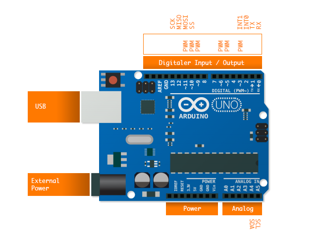
Pins des Arduino Boards
USB
USB is the serial interface that is used to program the Arduino. The Arduino is also supplied with power via this interface. Further information under [USB interface]
External power supply
If the Arduino is to run without a computer, then this connection can be used to supply the Arduino with power from a 7 to 12-volt battery or power supply.
Digital input / output
These pins can be used to recognise and control digital signals (see Digitaler Input, Digitaler Output).
Analog Input
These pins can be used to read out sensor values (see Analog Input). Two of these pins (A4 and A5) also play an important role in communication via the I2C (de) interface.
Power
Hier sind alle Pins versammelt, welche für die grundlegende Spannungsversorgung benötigt werden. Es gibt GND, 5V, 3.3V und Vin.
PWM
These pins are used for Pulse Width Modulation (PWM).
SDA / SCL
These pins are used for the so-called I2C interface, which can be used to read digital sensors and control other peripherals.
RX / TX
These two Pins are for Serielle Kommunikation and are also used for the USB connection to the computer.
INT0 / INT1
These two pins are called interrupts. This allows you to use a Interrupt Service Routine to recognise events that take place very quickly.
SCK / MISO / MOSI / SS
These four pins are required for communication via the SPI interface. A common application example is controlling a shift register with Shift Registers.
Special Functions
setup()
Called only once at the beginning of the program. Some special functions should be called here (e.g. pinMode ()).
loop ()
The loop contains the actual program and is executed infinitely. The speed at which the program is called depends on the clock frequency of the processor and the functions that are called.
pinMode (PIN)
Defines whether a PIN is used as an input or output
digitalRead (PIN)
Reads the value on a digital PIN (previously defined as an input)
digitalWrite (PIN, value)
Sets output value for a PIN (previously defined as an output)
analogRead (PIN)
Reads the value of an analogue PIN
analogWrite(PIN, Wert)
Sets the PWM value of a pin
delay(value)
Pauses the current program for a defined time (time is given in milliseconds). There are alternatives to delaying all the code, using the millis() function.
millis()
This returns the milliseconds elapsed since the programme started.
Further Information
- Getting Started with Arduino – Massimo Banzi (2008)
- Arduino – The Arduino Website.
- Microcontrollers – What's a microcontroller?