Aesthetic elements in Eagle
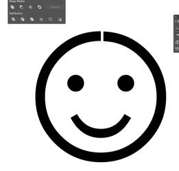
step 1: In illustrator, remove any composite shapes that include cutouts. You can create "virtual cutouts", by opening up the shape with a small gap using the Pathfinder tool. The image below is exaggerated, you should make the gap so small that you won't see it in the final PCB.
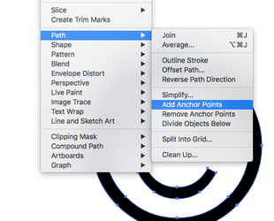
step 2: Curves aren't supported, so we will need to straighten the lines. But first, we can add additional vertices/points to the graphic so we end up with something close to our original graphics. Object>Path>Add Anchor Points. Try to find the minimum number of points where it still looks like the original graphic. This might take a couple of attempts.
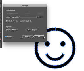
step 3: Remove any curves by reducing to straight lines using Object>Path>Simplify
step 4: Export as a DXF file
step 5: Place the file in Eagle with the "import_dxf_polygons_v4.ulpf" ulp script
step 6: Select the Polygon option from the drop-down menu, and scale the graphic if need be. Select which layer you want it to appear on, which will likely be either the "top" or "bottom" layer.
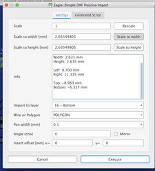
step 7: You will be prompted to give a signal name for each polygon. Give them all the same name, one which is not shared by any signal on your PCB
step 8: Hit the rats-nest button and see your new graphics.