Shift Registers
Shifting out is a method in which individual bits are "shifted" - i.e. written out - one after the other via a pin of an Arduino. This function can be used for example to control multiple LEDs with just a few pins.
Background
To understand how shifting out works, it helps to imagine the basic operations of the microcontroller. A microcontroller - like any other CPU - only works on the basis of 0 (OFF) and 1 (ON). A byte consists of eight bits.
In one byte we can store up to 256 unique values (from 0 to 255).
0000 0000 = 0
0000 0001 = 10000 0010 = 20000 0011 = 30000 0100 = 40000 0101 = 5
...1111 1111 = 255 The value of the byte can either be determined by the sum of the values of the bits or each bit can be set directly. In C/C++ we have access to these values through some defined functions - through the so-called bitwise operations. For example, if you want to change the third bit in a byte, there are three options...
byte test = B00100000; // We can writes bits directly with this notationbyte test = 40; // We can writes the decimal sum of all bites like this byte test = bitWrite(test, 3, HIGH); // we can set individual bits like this
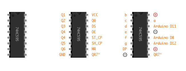
If we now imagine that each bit represents an LED, which is set ON or OFF depending on the value of the bit, then we can control eight different LEDs with the help of one byte. So it's just a matter of how we can send a byte and then decode it in such a way that we can use it to switch an LED. For this, we use a shift-register, specifically the 75HC595. This allows us to send the entire byte via one data PIN (DATA_PIN) and to switch up to eight outputs depending on its value. We can even stack shift-registers together to get even more outputs from just one pin.
The function shift out(DATA_PIN, CLOCK_PIN, bitOrder, value) takes over the timing and the writing out of the complete byte. DATA_PIN is the PIN via which the data is sent. CLOCK_PIN is for timing. bitOrder describes whether we want to read the byte from left to right (MSBFIRST - most significant bit first) or from right to left (LSBFIRST - last significant bit first).
Example
A good tutorial on using a shift register is documented here. The following components are required for the tutorial:
1x Arduino
1x Shift Register 74HC595 (Data-sheet)
1x Display Kingsbright (Data-sheet)
2x Mini Breadboards
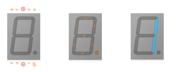
The display actually consists of 8 individual LEDs, which are arranged in the form a numeric segment display. The corresponding connections are located on the back of the display. In the data sheet of the display we find the information how these connections have to be assigned.
In order to address the shift register, we first need to look at the timing of the register. There is a so-called timing diagram in the data sheet for the 74HC595.
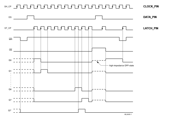
Using this diagram, it can be seen that we first need to set the LATCH_PIN to LOW. Then the data can be shifted to the register. Finally, the LATCH_PIN is set HIGH again to set the outputs of the register and to light up the LEDs.
The first example shows how a byte is resolved at the bit level. The following example helps to really be able to address each individual pin of the register.
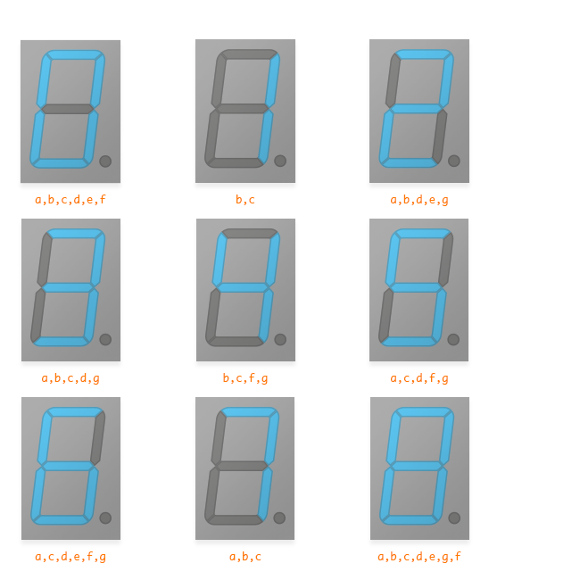
If we want to display all digits correctly, we have to create a small table that shows us the LEDs that have to be switched on for the respective digit. This results in the following visualisation.
Exercises
1. Displays all digits from 0-9 on the 7-segment display
2. Simplify your code so that you only have one array in which the digits and the corresponding LEDs are stored.
3. Supplements the code so that you can also display letters in addition to the numbers.