Exercises 2019
This page will be populated with all exercises given in the class. Use it as a reference for compiling your documentation
17.09.2019
Exercise 1.1: Electricity
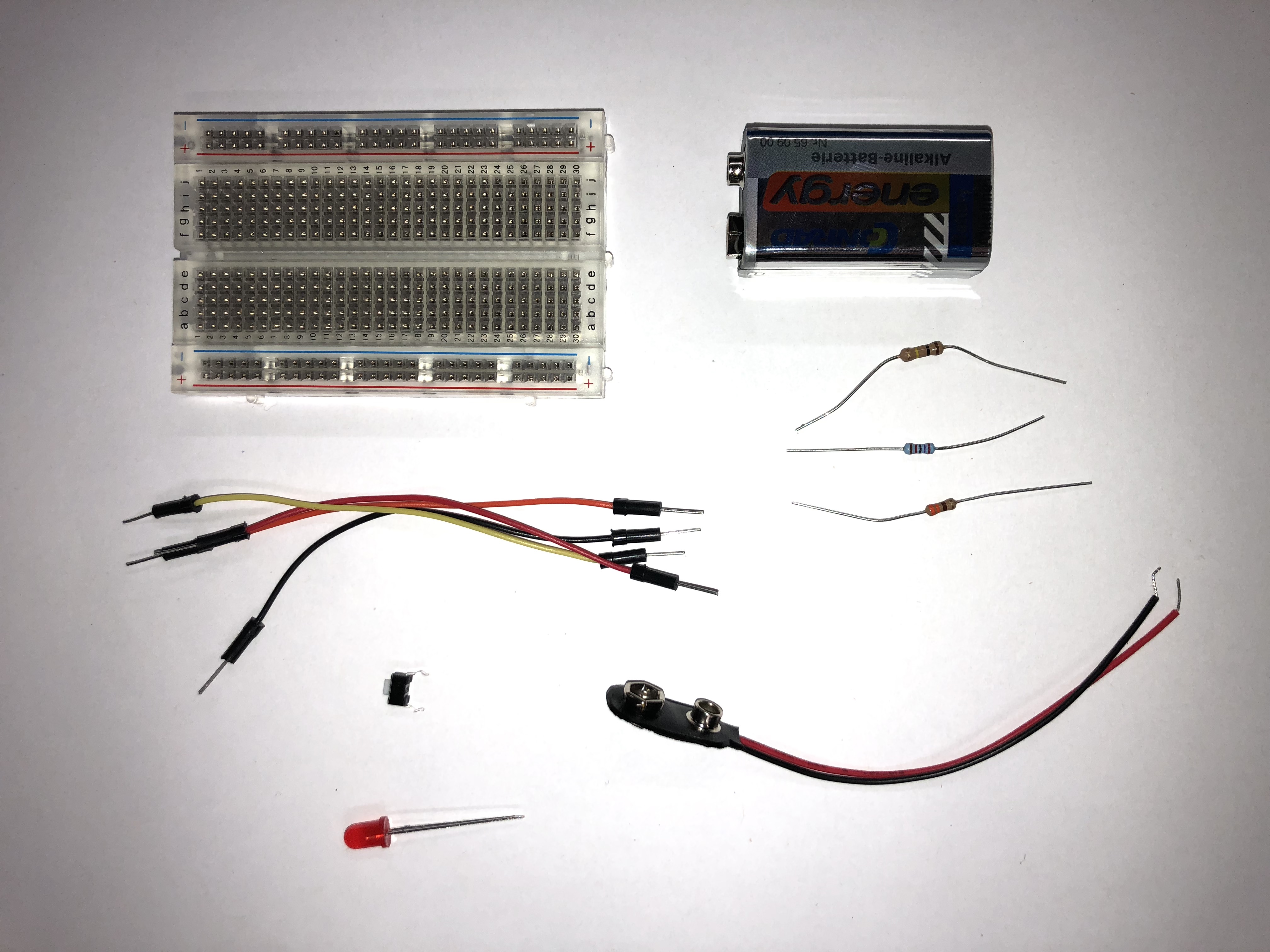
Using some of the following materials, create a circuit that lights up the LED. Photograph your outcome and draw a schematic. Here's an Image of the material to help find them.
- Tactile switch
- Jumper wires
- Breadboard
- LED (red)
- Resistors
- 9-volt battery
- 9-volt battery holder
Exercise 1.2: Digital Output
Install the Arduino IDE and find the "Blink" sketch in examples. Expand the example to sequence three external LEDs with appropriate resistors.
Exercise 1.3: Digital Input
Control two LEDs with buttons. Find the "Button" Sketch in the digital examples in the Arduino IDE. Hook up the appropriate hardware in order to use the sketch, and modify the code to control each LED with its own button.
18.09.2019
Exercise 2.1: Toggle switch
Using the "Button" Sketch again, modify the code so that one press turns one LED on, and another press turns one LED off.
Did the circuit work as you expected? If not, think about what might be causing it to behave strangely.
Exercise 2.2: Analog Input
Use a potentiometer to control the speed of a flashing LED.
Exercise 2.3: Analog Sensor & PWM
Use a circuit with a photoresistor to control the brightness of an LED.
Exercise 2.4: Smoothing Analog values and Serial port
Reuse the previous circuit and modify your code to get your values over the serial terminal. Use a moving average algorithm or a weighted moving average algorithm to smooth out the values.
Exercise 2.5: Soldering
Solder your own micro-interaction ball. Don't forget to draw a schematic of the circuit from the PCB.
19.09.2019
Exercise 3.1 Transistors
Use a transistor to control a small motor with the Arduino. Hook up a suitable input component to control the motor.
Exercise 3.2 Servo Motors
Exercise 3.2: Integrated Circuit
a) In the first part, try to understand how an H-Bridge IC works and find the data-sheet for your specific component in the box. Then draw a simple wiring schematics of an H-Bridge circuit to drive one motor with an Arduino. You can draw it by hand, in a tool of your choice or create a tinker circuit at https://www.tinkercad.com/circuits/.
Hint: The L293D H-Bridge in TinkerCad shares the same pin-mapping with the SN754410.
b) Implement the code for the Arduino to control the motor. It should be possible to start and stop the motor and to control the drive direction through a button click. After implementing these basics methods, think about how it is possible to control the motor speed with the H-Bridge.
Exercise 3.3: Arduino & Processing
In the last exercise, you learned how to control a direct current motor with an H-Bridge IC. To further work on this project without the need for an actual motor, it would be great to have a visual representation of the motor state.
Send the motor state (speed, direction) through Serial to a Processing application. The Processing receives these parameters and visualizes the state of the motor, which could look like the following image:
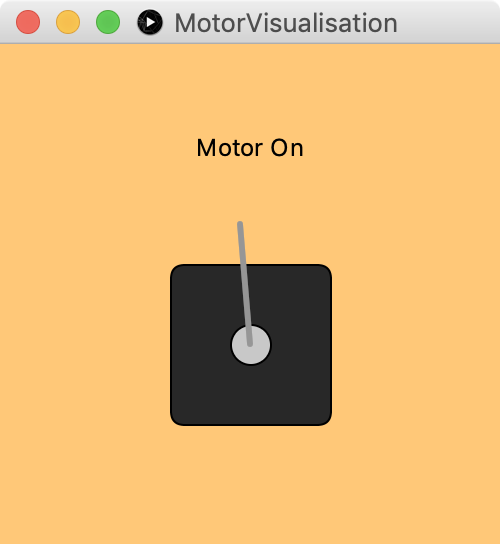
In the beginning, it is ok just to display text which represents the motor state.
Advanced Task: Try to send commands back to the Arduino and control the motor if the user presses a key on the keyboard.
20.09.2019
Exercise 4.1: Digital Components
a) Connect the Ultrasonic Distance Sensor and read distances with the help of the NewPing library. Log the distances to the Serial Monitor.
b) Add the NeoPixel LEDs to the circuit and display the current distance on them.
Advanced: Use an LCD screen to display to measured distance.