Electronics Basics (EN)
In order to use electronics and microcontrollers successfully for projects, we need to understand some electronic terms and theories. These include:
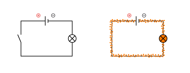
Electronic Circuit: A circuit is a sequence of connected electronic components. The simplest electrical circuit consists of a power source, a load and the connecting lines (conducting wires). Electric current can only flow in a closed circuit. In a closed circuit, the current flows from the negative pole of the power source to the positive pole.
Electrons: Electrons are negatively charged sub-atomic (smaller than atoms) particles that can balance positively charged particles (protons) to create an equilibrium (same number of electrons and protons, i.e no charge). This property of attraction between electronics and protons can cause electronics to move or flow inside an electrical circuit.
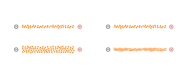
Current (measured in ampers): Current describes the rate of flow of electrons in a conductor. The greater the number of electrons, the higher the measured current.
Voltage (measured in volts): Voltage describes the strength with which the electrons "flow" in a certain direction. There are both positive and negative voltages.
Resistance (measured in Ohm): Resistance describes the property of materials to restrict the flow of electrons to a greater or lesser extent.
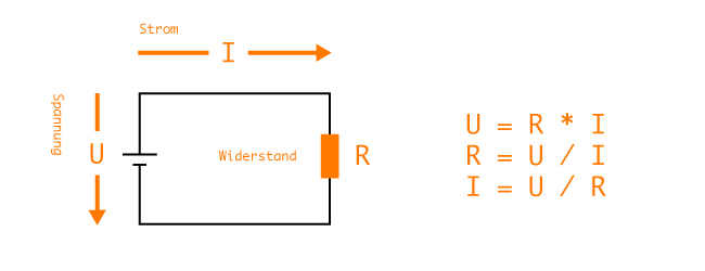
Ohm's law (U = R x I): Ohm's law describes the relationship between current (I), voltage (U) and resistance (R). If a resistor is connected to a power supply to form a closed circuit, a certain current will flow through the resistor. The strength of this current depends on the applied voltage and the resistance. With the help of Ohm's law, the three basic quantities in an electric circuit can be determined if two quantities are known.
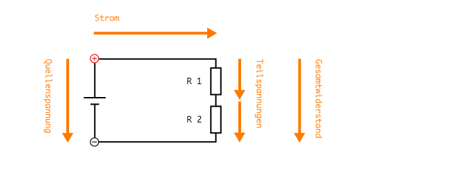
Series circuit (Rges = R1 + R2 + R3 + ...): In a series circuit resistors are in succession, and the same current flows through all components when a voltage is applied. Here, the sum of all resistors gives the total resistance. The voltage measured between the resistors is a ratio from the resistance between positive and negative terminals. This circuit could also be called a voltage divider.
Example series connection:
Known Values
R1 = 60Ω, R2 = 120Ω, U = 12V
Known Values
Rges, I, U1, U2
Solution
Rges = R1 + R2 = 60Ω + 120Ω = 180Ω
I = U / Rges = 12V / 180Ω = 0.067 A
U1 = I * R1 = 0.067A * 60Ω = 4V
U2 = I * R2 = 0.067A * 120Ω = 8V
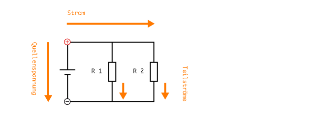
Parallel circuit: In contrast to the series connection, the same voltage (U) is applied to all components in this parallel circuit. However, the total current is distributed unevenly to the loads/resistors. This is can also be called a current divider.
Most real-world circuits combine many components in both parallel and series.
Direct current (DC): Direct current refers to an electronic current that does not change in direction and strength.
Alternating current (AC): Alternating current is an electrical current that changes its direction (polarity) at regular intervals. Alternating current also includes, for example, the current from the socket that oscillates at about 50Hz and at 230 volts.
ATTENTION: UNDER NO CIRCUMSTANCES WILL WE EVER USE THE ALTERNATING CURRENT FROM THE SOCKET!
Dangers:
If you are working on a circuit, disconnect the power supply first!
We only use voltages up to 12V, never above!
When using soldering irons, special care is required not to burn yourself, or melt a hole in high voltage cables
Further Resources
Elektronik Grundlagen - Elektronik Kompendium
Electronic Basics - ITP Physical Computing
Adventures in Science! - Sparkfun
Resistor Basics - Sparkfun
Voltage Divider - Sparkfun
Ohms Law - Sparkfun