Transistors as Switches
When we talk about "transistors", we usually mean a bipolar transistor. Transistors consist of semiconductors, which means they can transition from conducting to non-conducting. These properties can be used as a kind of electrically activated "switch". This makes it possible to switch larger loads with small ones. This can be really useful, for example, if a larger relay, motor or lightbulb needs to be switched with an Arduino board.
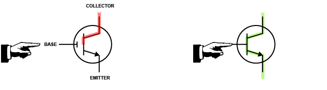
You can imagine the transistor like a switch. When the switch is pressed, the current flows. If the switch is released, the current no longer flows. The transistor has three connections: Base, Emitter and Collector. The voltage at the base-emitter switches the collector-emitter path. The circuit of a transistor depends on its type. There are two main types of transistors: NPN and PNP transistors. The current direction (collector-emitter) must be observed, otherwise, the transistor could be damaged. We will use NPN transistor most of the time.
Here is a drawing from the Datasheet of the TIP 122, which shows where base, emitter and collector pins can be found

The following diagram visualizes the current flow (I/red) and the voltage flow (U/blue) which are applied to the transistor. Important: A base resistor (RB) and a load are always required for correct operation.
![]()
UCE = Collektor-Emitter-Voltage
UE = Driving Voltage
UBE = Base-Emitter-Voltaege (Threshold value)
IC = Collector Current
IB = Base current
RB = Base resistor
The Transistor as a Switch
A common use of a transistor is in the switching of higher loads - since most microcontrollers are limited in their output power on digital pins. For example, the Arduino can switch a load of 5V at 20mA per output. This is enough for LED's and maybe a small vibration motor. However, if a fan, a high power LED, a solenoid, a motor, etc. is connected you definitely need a transistor circuit. In this case, the transistor works similar to a relay: it switches higher loads with smaller loads. A distinction must also be made between switching non-inductive loads (e.g. LED) and inductive loads (e.g. fan, relay, motor). An inductive load will probably need a Fly Back Diode.
Switching a non-inductive Load
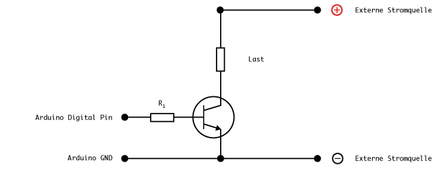
For switching a non-inductive load, the transistor circuit is very simple to set up. You only need an NPN transistor (TIP 122) and a series resistor in the path IB (1 kOhm). The circuit diagram looks as follows:
R1 = 1 kOhm (approximate value)
Transistor = TIP 122
Example
In this example, we want to light up the RGB LED strip and control its brightness. According to the labelling and datasheet, the strip needs 12V supply voltage - corresponding resistors are already present and soldered on the strip. To realize this circuit we need a 12V power supply, one transistor (TIP 122 NPN) per channel, one resistor (1kOhm) per channel and the Arduino.
The following setup is needed to control a single color (here red)...
We program the Arduino with the following example code, which fades the red channel back and forth.
Exercise
Extend the previously developed circuit so that all three channels of the RGB LED strip can be controlled differently.
Program a colour change that fades between red, green and blue (logic: off>red>green>blue>off).
Further Information
Make Presents: The Transistor
Bipolarer Transistor
Der Transistor als Schalter